Fuse Box Ford 2002 F-350 Diesel Junction Diagram
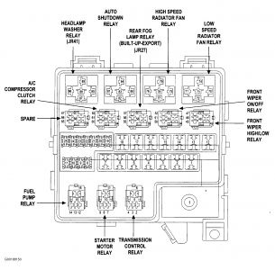
Fuse Panel Layout Diagram Parts: generic electronic module GEM connection, one touch down relay, accessory delay relay, interior lamp relay, horn relay.




 Assuming
 Inductor
 |
| 1967-69 Chevrolet Camaro Wirng Diagram |

This circuit is similar to the one above but uses positive feedback to get a little more amplitude to the speaker. I copied it from a small 5 transistor radio that uses a 25 ohm speaker. In the circuit above, the load resistor for the driver transistor is tied directly to the + supply. This has a disadvantage in that as the output moves positive, the drop across the 470 ohm resistor decreases which reduces the base current to the top NPN transistor. Thus the output cannot move all the way to the + supply because there wouldnt be any voltage across the 470 resistor and no base current to the NPN transistor.
This circuit corrects the problem somewhat and allows a larger voltage swing and probably more output power, but I dont know how much without doing a lot of testing. The output still wont move more than a couple volts using small transistors since the peak current wont be more than 100mA or so into a 25 ohm load. But its an improvement over the other circuit above.
In this circuit, the 1K load resistor is tied to the speaker so that as the output moves negative, the voltage on the 1K resistor is reduced, which aids in turning off the top NPN transistor. When the output moves positive, the charge on the 470uF capacitor aids in turning on the top NPN transistor.
The original circuit in the radio used a 300 ohm resistor where the 2 diodes are shown but I changed the resistor to 2 diodes so the amp would operate on lower voltages with less distortion. The transistors shown 2n3053 and 2n2905 are just parts I used for the other circuit above and could be smaller types. Most any small transistors can be used, but they should be capable of 100mA or more current. A 2N3904 or 2N3906 are probably a little small, but would work at low volume.
The 2 diodes generate a fairly constant bias voltage as the battery drains and reduces crossover distortion. But you should take care to insure the idle current is around 10 to 20 milliamps with no signal and the output transistors do not get hot under load.
The circuit should work with a regular 8 ohm speaker, but the output power may be somewhat less. To optimize the operation, select a resistor where the 100K is shown to set the output voltage at 1/2 the supply voltage (4.5 volts). This resistor might be anything from 50K to 700K depending on the gain of the transistor used where the 3904 is shown.


This circuit emits a beep and/or illuminates a LED when someone touches the door-handle from the outside. The alarm will sound until the circuit will be switched-off.
The entire circuit is enclosed in a small plastic or wooden box and should be hanged-up to the door-handle by means of a thick wire hook protruding from the top of the case.
A wide-range sensitivity control allows the use of the Door Alarm over a wide variety of door types, handles and locks. The device has proven reliable even when part of the lock comes in contact with the wall (bricks, stones, reinforced concrete), but does not work with all-metal doors. The LED is very useful during setup.
 Door Alarm Circuit diagram
Parts:
R1______________1M   1/4W Resistor
R2______________3K3  1 or 2W Resistor (See Notes)
R3_____________10K   1/2W Trimmer Cermet (See Notes)
R4_____________33K   1/4W Resistor
R5____________150K   1/4W Resistor
R6______________2K2  1/4W Resistor
R7_____________22K   1/4W Resistor
R8______________4K7  1/4W Resistor

C1,C2__________10nF   63V Ceramic or Polyester Capacitors
C3_____________10pF   63V Ceramic Capacitor
C4,C6_________100nF   63V Ceramic or Polyester Capacitors
C5______________2µ2   25V Electrolytic Capacitor
C7____________100µF   25V Electrolytic Capacitor
D1,D2,D4_____1N4148   75V 150mA Diodes
D3_____________5 or 3mm. Red LED

Q1,Q2,Q3,Q5___BC547   45V 100mA NPN Transistors
Q4____________BC557   45V 100mA PNP Transistor

L1_________________   (See Notes)
L2_____________10mH  miniature Inductor

Hook_______________   (See Notes)

BZ1___________Piezo sounder (incorporating 3KHz oscillator)

SW1,SW2________SPST  miniature Slider Switches

B1_______________9V  PP3 Battery

Clip for PP3 Battery
Circuit operation:
Q1 forms a free-running oscillator: its output bursts drive Q2 into saturation, so Q3 and the LED are off. When part of a human body comes in contact with a metal handle electrically connected to the wire hook, the body capacitance damps Q1 oscillations, Q2 biasing falls off and the transistor becomes non conducting. Therefore, current can flow into Q3 base and D3 illuminates. If SW1 is closed, a self-latching circuit formed by Q4 & Q5 is triggered and the beeper BZ1 is activated.
When the human body part leaves the handle, the LED switches-off but the beeper continues to sound, due to the self-latching behavior of Q4 & Q5. To stop the beeper action, the entire circuit must be switched-off opening SW2. R3 is the sensitivity control, allowing to cope with a wide variety of door types, handles and locks.
Notes:
Source : www.redcircuits.com

