Wednesday, March 27, 2013

Valve Sound Converter

‘Valve sound’ is not just an anachronism: there are those who remain ardent lovers of the quality of sound produced by a valve amplifier. However, not everyone is inclined to splash out on an expensive valve output stage or complete amplifier with a comparatively low power output. Also, for all their aesthetic qualities, modern valve amplifiers burn up (in the full sense of the word!) quite a few watts even at normal listening volume, and so are not exactly environmentally harmless. This valve sound converter offers a cunning way out of this dilemma. It is a low cost unit that can be easily slipped into the audio chain at a suitable point and it only consumes a modest amount of energy.
Valve Sound Converter-Circuit diagram
A valve sound converter can be constructed using a common-or-garden small-signal amplifier using a readily-available triode. Compared to using a pentode, this simplifies the circuit and, thanks to its less linear characteristic, offers even more valve sound. For stereo use a double triode is ideal. Because only a low gain is required, a type ECC82 (12AU7) is a better choice than alternatives such as the ECC81 (12AT7) or ECC83 (12AX7). This also makes things easier for home brewers only used to working with semiconductors, since we can avoid any difficulties with high voltages, obscure transformers and the like:the amplifier stage uses an anode voltage of only 60 V, which is generated using a small 24 V transformer and a voltage doubler (D3, D4, C4 and C5).
Since the double triode only draws about 2mA at this voltage, a 1 VA or 2 VA transformer will do the job. To avoid ripple on the power supply and hence the generation of hum in the converter, the anode voltage is regulated using Zener diodes D1 and D2, and T1. The same goes for the heater supply: rather than using AC, here we use a DC supply, regulated by IC1. The 9 V transformer needs to be rated at at least 3 VA. As you will see, the actual amplifier circuit is shown only once. Components C1 to C3, R1 to R4, and P1 need to be duplicated for the second channel.
Valve Sound Converter-w
The inset valve symbol in the circuit diagram and the base pinout diagram show how the anode, cathode and grid of the other half of the double triode (V1.B) are connected. Construction should not present any great difficulties. Pay particular attention to screening and cable routing, and to the placing of the transformers to minimise the hum induced by their magnetic fields. Adjust P1 to set the overall gain to 1 (0 dB). The output impedance of 47 kΩ is relatively high, but should be compatible with the inputs of most power amplifiers and preamplifiers.

For a good valve sound, the operating point of the circuit should be set so that the audio output voltage is in the region of a few hundred millivolts up to around 1.5 V. If the valve sound converter is inserted between a preamplifier and the power amplifier, it should be before the volume control potentiometer as otherwise the sound will change significantly depending on the volume. As an example, no modifications are needed to an existing power amplifier if the converter is inserted between the output of a CD player and the input to the amplifier.


http://www.ecircuitslab.com/2012/04/valve-sound-converter.html
Continue Reading[..]

Car Alarm Sound Booster

For car alarms, emphasis should be put on hearing the audible alert and identifying it as belonging to your ‘wheels’. Unfortunately, modern car alarm systems seem to have more or less the same alarm sound especially if they are from the same brand. Also, to comply with legal noise restrictions, the alarm sound is not always loud enough to be heard if the car is parked down the road.

The circuit shown here is designed to help boost the alarm sound by also activating the car’s horn(s) when the alarm goes off.Internally the car alarm system often provides a signal that activates the (optional) engine immobilizer and/or volume (ultrasound) sensors. This signal usually goes Low upon system triggering and high again when the alarm system is deactivated.

Car Alarm Sound Booster Circuit Diagram :

Car Alarm Sound Booster-Circuit Diagram

The alarm activation signal is fed to the circuit through D1. When in idle state, T1’s gate is High and consequently the FET conducts, keeping power FET T2 firmly switched of f. When the system gets an active low signal, T1 switches of f allowing timing capacitor C2 to charge via R2. About 15 seconds later, when the voltage across C2 is high enough, T2 starts to conduct and relay RE1 is energized. This, in turn, provides the required path for the ‘lights flashing’ signal to energize RE2 and feed battery power to the car’s horn(s).

When the alarm system is turned off the activation signal returns to High. T1 starts to con-duct and rapidly discharges C2 via R3. T2 is then cut off and RE1 is de-energized. Diode D2 suppresses back EMF from RE1.The circuit draws less than 2 mA when idling. When activated the circuit’s current consumption is virtually that of the RE1 coil.RE1 is any simple SPST or SPDT relay, capable of switching about 0.5 A (at 12 V). The coil rating is for 12 VDC and a current requirement as low as you can find. Fuse F1 should be a slow blow type and rated about twice RE1’s coil current.

The BS170 in position T2 can sink a continuous current of about 0.5 A. However, a value of 1.2 A pulsed is specified by Fairchild for their devices. To keep the FET’s d-s current due to C2 discharging within safe limits, R2 may be increased, C2 decreased and R3 increased, all proportionally. A factor of 2 will keep the FET out of harm’s way with maybe a slight change in the 15-second delay and the sensitivity of the circuit.C1 is used as a smoothing capacitor and F2 should be rated in accordance with the horn(s) maximum current draw.

Caution.The installation and use of this circuit may be subject to legal restrictions in your country, state or area.

Source : ecircuitslab.com

Continue Reading[..]

Door Alarm Circuit

Hangs up on the door-handle Beeps when someone touches the door-handle from outside

This circuit emits a beep and/or illuminates a LED when someone touches the door-handle from the outside. The alarm will sound until the circuit will be switched-off.
The entire circuit is enclosed in a small plastic or wooden box and should be hanged-up to the door-handle by means of a thick wire hook protruding from the top of the case.
A wide-range sensitivity control allows the use of the Door Alarm over a wide variety of door types, handles and locks. The device has proven reliable even when part of the lock comes in contact with the wall (bricks, stones, reinforced concrete), but does not work with all-metal doors. The LED is very useful during setup.

Circuit diagram:

Door Alarm Circuit diagram Door Alarm Circuit diagram
Parts:

R1______________1M   1/4W Resistor
R2______________3K3 1 or 2W Resistor (See Notes)
R3_____________10K 1/2W Trimmer Cermet (See Notes)
R4_____________33K 1/4W Resistor
R5____________150K 1/4W Resistor
R6______________2K2 1/4W Resistor
R7_____________22K 1/4W Resistor
R8______________4K7 1/4W Resistor

C1,C2__________10nF 63V Ceramic or Polyester Capacitors
C3_____________10pF 63V Ceramic Capacitor
C4,C6_________100nF 63V Ceramic or Polyester Capacitors
C5______________2µ2 25V Electrolytic Capacitor
C7____________100µF 25V Electrolytic Capacitor


D1,D2,D4_____1N4148   75V 150mA Diodes
D3_____________5 or 3mm. Red LED

Q1,Q2,Q3,Q5___BC547 45V 100mA NPN Transistors
Q4____________BC557 45V 100mA PNP Transistor

L1_________________ (See Notes)
L2_____________10mH miniature Inductor

Hook_______________ (See Notes)

BZ1___________Piezo sounder (incorporating 3KHz oscillator)

SW1,SW2________SPST miniature Slider Switches

B1_______________9V PP3 Battery

Clip for PP3 Battery


Circuit operation:


Q1 forms a free-running oscillator: its output bursts drive Q2 into saturation, so Q3 and the LED are off. When part of a human body comes in contact with a metal handle electrically connected to the wire hook, the body capacitance damps Q1 oscillations, Q2 biasing falls off and the transistor becomes non conducting. Therefore, current can flow into Q3 base and D3 illuminates. If SW1 is closed, a self-latching circuit formed by Q4 & Q5 is triggered and the beeper BZ1 is activated.

When the human body part leaves the handle, the LED switches-off but the beeper continues to sound, due to the self-latching behavior of Q4 & Q5. To stop the beeper action, the entire circuit must be switched-off opening SW2. R3 is the sensitivity control, allowing to cope with a wide variety of door types, handles and locks.


Notes:


  • L1 is formed winding 20 to 30 turns of 0.4mm. diameter enameled copper wire on R2 body and soldering the coil ends to the resistor leads. You should fill R2 body completely with coil winding: the final turns number can vary slightly, depending on different 1 or 2W resistor types actual length (mean dimensions for these components are 13 - 18mm. length and 5 - 6mm. diameter).


  • The hook is made from non-insulated wire 1 - 2mm. diameter (brass is well suited). Its length can vary from about 5 to 10cm. (not critical).


  • If the device is moved frequently to different doors, Trimmer R3 can be substituted by a common linear potentiometer fitted with outer knob for easy setup.


  • To setup the device hang-up the hook to the door-handle (with the door closed), open SW1 and switch-on the circuit. Adjust R3 until the LED illuminates, then turn slowly backwards the screwdriver (or the knob) until the LED is completely off. At this point, touching the door-handle with your hand the LED should illuminate, going off when the hand is withdrawn. Finally, close SW1 and the beeper will sound when the door-handle will be touched again, but will not stop until SW2 is opened.


  • In regular use, it is advisable to hang-up and power-on the device with SW1 open: when all is well settled, SW1 can be closed. This precautionary measure is necessary to avoid unwanted triggering of the beeper.


Source : www.redcircuits.com

Continue Reading[..]

Tuesday, March 26, 2013

Automatic Emergency Light

This is the simple circuit of automatic emergency light. It is called dark dependent circuit. A 555 timer IC and LDR is used for this configuration. When light fall on the LDR, its resistance is decrease and in dark position its resistance is going high. Using these characteristics of LDR, automatic emergency light is made.

Automatic Emergency Light Circuit diagram:

Automatic Emmergency Light

LDR is called Light Dependent Resistor. Its resistance is inversely proportional to the falling light on its surface. In dark, its resistance is approximately 7k to 10k. When light fall on its surface, its resistance is decrease to less than 1k. In the circuit, a voltage divider arrangement circuit is used here with LDR and 10K variable resistor.

When light fall on the surface of LDR, the resistance decrease to 1k. So the voltage of the timer pin-6 is greater than 2/3 of +Vcc. For this reason the output pin-3 goes low. The base voltage of transistor BC547 is less than 0.75 volt. The transistor is OFF state. So the light is OFF. In dark position the LDR resistance increase is high so the voltage of the trigger pin-2 decrease to less than 1/3 of +Vcc. The output pin-3 goes high so the base voltage of the transistor BC547 is greater than 0.75 volt. The transistor is ON state. So the light is ON and it emits light.

Source: http://www.ecircuitslab.com/2012/06/simple-automatic-emergency-light.html
Continue Reading[..]

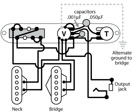
Explain Tele Reissue Selector Switchtelecaster Guitar Forum

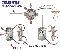
 Switch Wiring Diagram on Way Switch   Feed To Switch
Way Switch Feed To Switch.


 Switch Wiring Diagram on Electrical Wiring In The Home  Three Way Switch To A Split Recepticle
Electrical Wiring In The Home Three Way Switch To A Split Recepticle.


 Switch Wiring Diagram on Explain 52 Tele Reissue Selector Switch   Telecaster Guitar Forum
Explain 52 Tele Reissue Selector Switch Telecaster Guitar Forum.


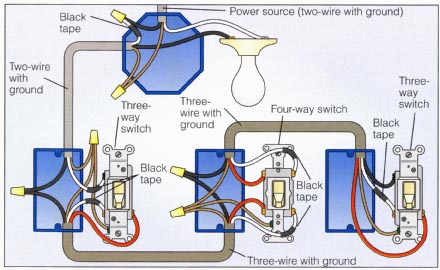
 Switch Wiring Diagram on Way Switch Wiring Diagram  Power Enters At One 3 Way Switch Box
Way Switch Wiring Diagram Power Enters At One 3 Way Switch Box.


 Switch Wiring Diagram on Way Switch With Lights Wiring Diagram
Way Switch With Lights Wiring Diagram.


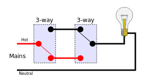
 Switch Wiring Diagram on Way Switches Position 1 Svg
Way Switches Position 1 Svg.


 Switch Wiring Diagram on Double Pole Switch Wiring Diagram   Electrical Information Blog   Pc
Double Pole Switch Wiring Diagram Electrical Information Blog Pc.


 Switch Wiring Diagram on Way Wiring  Ceiling Fan With Remote For Two Wire Hookup   Electrical
Way Wiring Ceiling Fan With Remote For Two Wire Hookup Electrical.


 Switch Wiring Diagram on Way Switching Electric Guitar Wiring Diagram
Way Switching Electric Guitar Wiring Diagram.


 Switch Wiring Diagram on Fixtures How Three Way Switches Work Garbage Disposal Wiring Gallery 3
Fixtures How Three Way Switches Work Garbage Disposal Wiring Gallery 3.


Continue Reading[..]

Monday, March 25, 2013

AUDIO POWER METER WITH LM3915


This VU (volume-unit) meter is capable of monitoring anddisplaying power
levels present at the speaker terminals ofan stereo audio power
amplifier.

The levels are displayed in ten discrete steps. This meter is not
designed to give an accurate display of the power levels.It is designed
to give an approximate visual indication of the audio power output of
each channel. For many situations - disco, parties - this is all which
is required: the flashing LED's add atmosphere to the situation.

LM3915. This is a monolithic Dot/Bar Display Driver IC made by National
Semiconductor. It takes an analog voltage input on pin 5 then drives 10
LED's providing a logarithmic 3dB/step analog display. When measuring
power, a 3dB increase means that the power input has doubled. As the
power doubles, an additional LED will be lit until the maximum is
reached. The display can be bar or moving dot depending on the
connection of pin 9 to the positive supply. The LED drive current is
regulated which eliminates the need for current limiting resistors.

The supply voltage can be between 3V to 25V. You can download the data sheet from the National Semiconductor website at: http://www.national.com/

The IC is suited to signals with a wide dynamic range such as audio,
power, light intensity. In many applications a bargraph meter is faster,
more rugged and has higher visibility than an analog (moving coil) or
LCD meter.


PARTS LIST


R1-----10K

R2------1K

R3-----390

R4-----2,7K

P1-----100K TRIMMER POT.

C1-----10mf 25v

D1..D10---LED red

I.C. ----LM3915
Continue Reading[..]

Bright Switching Lights Dull Darkwiring

Light Switch Wiring on Talimba   Images   2 Way Switch Wiring
Talimba Images 2 Way Switch Wiring.


Light Switch Wiring on How To Wire A Switch   Light Then Switch And Outlet
How To Wire A Switch Light Then Switch And Outlet.


Light Switch Wiring on Is Bright And Switching Lights On When It Is Dull Or Dark  Wiring
Is Bright And Switching Lights On When It Is Dull Or Dark Wiring.


Light Switch Wiring on Way Switch Wiring Diagram
Way Switch Wiring Diagram.


Light Switch Wiring on Home Wiring Guide   Single Way Lighting Circuit
Home Wiring Guide Single Way Lighting Circuit.


Light Switch Wiring on Wiring A Light Switch Diagram   Reviews And Photos
Wiring A Light Switch Diagram Reviews And Photos.


Light Switch Wiring on Wiring A Light Switch And Outlet   Howishow Answers Search Engine
Wiring A Light Switch And Outlet Howishow Answers Search Engine.


Light Switch Wiring on Rear Fog Light Switch Wiring   Nasioc
Rear Fog Light Switch Wiring Nasioc.


Light Switch Wiring on Light Switch Wiring Diagram
Light Switch Wiring Diagram.


Light Switch Wiring on Touch Plate Low Voltage Lighting Systems  Switches  Wall Switch Plates
Touch Plate Low Voltage Lighting Systems Switches Wall Switch Plates.


Continue Reading[..]