Showing posts with label remote. Show all posts
Showing posts with label remote. Show all posts
Saturday, April 13, 2013
Low Voltage Remote Mains Switch
This circuit allows a 240V mains appliance to be controlled remotely via low-voltage cabling and a pushbutton switch. The mains appliance (in this case, a light bulb) is switched with a suitably-rated relay. All of the electronics is housed in an ABS box located in proximity to the appliance. The pushbutton switch and plugpack are located remotely and can be wired up with 3-core alarm cable or similar. Cable lengths of 20m or more are feasible with this arrangement. When the switch (S1) is pressed, the input (pin 8) of IC1c is briefly pulled low via the 10mF capacitor, which is initially discharged.

Low-Voltage Remote Mains Switch Circuit Diagram
The output (pin 10) immediately goes high and this is inverted and fed back to the second input (pin 9) via another gate in the quad NAND package (IC1d). In conjunction with the 1MW resistor and 470nF capacitor, IC1d eliminates the effects of contact "bounce" by ensuring that IC1c’s output remains high for a predetermined period. The output from IC1c drives the clock input of a 4013 D-type flip-flop (IC2). The flipflop is wired for a "toggle" function by virtue of the Q-bar connection back to the D input. A 2.2MW resistor and 100nF capacitor improve circuit noise immunity. Each time the switch is pressed, the flipflop output (pin 13) toggles, switching the transistor (Q1) and relay on or off. Note that all mains wiring must be properly installed and completely insulated so that there is no possibility of it contacting the low-voltage side of the circuit.
http://streampowers.blogspot.com/2012/06/low-voltage-remote-mains-switch.html
Saturday, March 9, 2013
Hunter Company Remote Ceiling Blade Ceiling
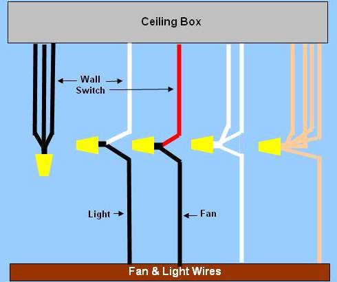
Ceiling Fan Power Enters At Switch Box Two Wall Switches For Light.

Hang The Ceiling Fan Connect Wires Secure Housing.

Hunter Fan Company Remote Ceiling Fan Blade Ceiling Fan And.
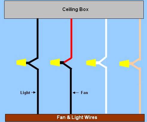
Ceiling Fan Power Enters At Ceiling Box Circuit Continues On Two.

Wiring Diagram For Ceiling Fan Capacitor Wiring Diagram For Ceiling.

Hunter Ceiling Fan With Light Fixture Wiring Diagram.
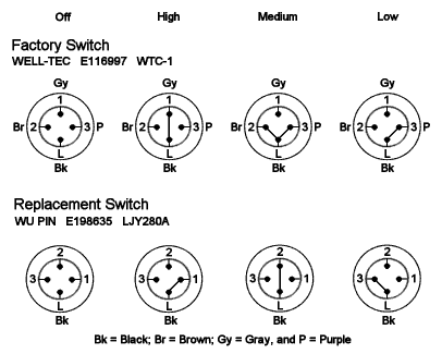
Hunter Ceiling Fan Control Switch And Help With Hunter Ceiling Fan.

Hunter Fan Remote Wiring Diagram Hunter Fan Remote Wiring Diagram.

Purchased A Ceiling Fan With A Light Kit To Replace One That Fixya.

Peugeot 306 Cooling Fan Wiring Diagram Thumb Png.
Subscribe to:
Posts (Atom)