Wednesday, December 25, 2013
Two Wire Temperature Sensor
Remote temperature measurements have to be linked by some sort of cable to the relevant test instrument. Normally, this is a three-core cable: one core for the signal and the other two for the supply lines. If the link is required to be a two-core cable, one of the supply lines and the signal line have to be combined. This is possible with, for instance, temperature sensors LM334 and LM335. However, these devices provide an output that is directly proportional to absolute temperature and this is not always a practical proposition.
Circuit diagram :

Two-Wire Temperature Sensor Circuit Diagram
If an output signal that is directly proportional to the celsius temperature scale is desired, the present circuit, which uses a Type LM45 sensor, offers a good solution. The LM45 sensor is powered by an alternating voltage, while its out-put is a direct voltage.
The supply to the sensor is provided by a sine-wave generator, based on A 1 and A 2 (see diagram). The alternating volt-age is applied to the signal line in the two-core cable via coupling capacitor C 6 .
The sensor contains a volt-age-doubling rectifier formed by D 1 -D 2 -C 1 -C 2 . This network converts the applied alternating voltage into a direct voltage. Resistor R 2 isolates the output from the load capacitance, while choke L 1 couples the output signal of the sensor to the signal line in the cable. Choke L 1 and capacitor C 2 protect the output against the alternating voltage present on the line.
At the other end of the link, network R 3 -L 2 -C 4 forms a low-pass section that prevents the alternating supply voltage from combining with the sensor out-put. Capacitor C 5 prevents a direct current through R 3 , since this would attenuate the temper-ature-dependent voltage.
The output load should have a high resistance, some 100 kΩ or even higher. The circuit draws a current of a few mA.
Monday, March 4, 2013
Trailer Wiring Diagram Light Plug Brakes Hitch Wire Brake
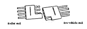
To Rv Wiring Wiring The 4 Pole Utility Trailer Plug.
Boat Wiring Illustrated Boat Wiring Illustrated Electrical.

Applications Small Boat Or Utility Trailers Any Trailer With Turn.

Family Pleasure And Fishing Boats For Sale Finance Like This One.

Trailer Wiring Electrical Connections Are Used On Car Boat And.

Trailer Wiring Diagram And Information Tridentuk Com.

More 1986 Bayliner Capri Wiring Diagram By Guto.

Terminal Number Function 7 Core Wire Colour 1 Reversing Light Yellow 2.

Trailer Wiring Diagram Light Plug Brakes Hitch 7 Pin Way Wire Brake.

All New Ck Trailer Tow Wiring Diagram Png.