Tuesday, April 30, 2013

10W Stereo Audio Amplifier Using TDA2009A

This is a schematic of a 10W stereo audio amplifier using TDA2009A amplifier IC. TDA2009A is a good IC provides quality sound. It has built in features like output current protection and thermal protection etc. The circuit can be operate between 8 to 24V DC with 1 to 2 amphere.

10W Stereo Audio Amplifier Circuit Diagram :
10w-stereo-amplifier-circuit-diagram

If you want to operate this 10 watt amplifier circuit with watt amplifier circuit with mains supply then use a filtered and stable power supply to reduce mains hum. 10 watt out put power can be obtained by providing 20V 1.5A to the circuit. Use good and thick heatsink with the IC.
Continue Reading[..]

Friday, April 26, 2013

Voltage Monitor

When the input voltage is 0 the LED glows. The LED stops glowing when the voltage rises to the level determined by R2. Reverse + and - pins to reverse operating mode. To set voltage at which LED goes off, (1) Set 0V at input. (2) Set input voltage at desired level. (3) Adjust R2 to point right after LED goes out.

Continue Reading[..]

Saturday, April 13, 2013

Low Voltage Remote Mains Switch

This circuit allows a 240V mains appliance to be controlled remotely via low-voltage cabling and a pushbutton switch. The mains appliance (in this case, a light bulb) is switched with a suitably-rated relay. All of the electronics is housed in an ABS box located in proximity to the appliance. The pushbutton switch and plugpack are located remotely and can be wired up with 3-core alarm cable or similar. Cable lengths of 20m or more are feasible with this arrangement. When the switch (S1) is pressed, the input (pin 8) of IC1c is briefly pulled low via the 10mF capacitor, which is initially discharged.

Circuit diagram:
low-voltage-remote-mains-switch-circuit-diagramw
Low-Voltage Remote Mains Switch Circuit Diagram

The output (pin 10) immediately goes high and this is inverted and fed back to the second input (pin 9) via another gate in the quad NAND package (IC1d). In conjunction with the 1MW resistor and 470nF capacitor, IC1d eliminates the effects of contact "bounce" by ensuring that IC1c’s output remains high for a predetermined period. The output from IC1c drives the clock input of a 4013 D-type flip-flop (IC2). The flipflop is wired for a "toggle" function by virtue of the Q-bar connection back to the D input. A 2.2MW resistor and 100nF capacitor improve circuit noise immunity. Each time the switch is pressed, the flipflop output (pin 13) toggles, switching the transistor (Q1) and relay on or off. Note that all mains wiring must be properly installed and completely insulated so that there is no possibility of it contacting the low-voltage side of the circuit.
 
 
http://streampowers.blogspot.com/2012/06/low-voltage-remote-mains-switch.html
Continue Reading[..]

Friday, April 12, 2013

PWM Dimmer Motor Speed Controller

This is yet some other mission born of necessity. Its a simple circuit, but does precisely what its designed to do - dim LED gentles or management the rate of 12V DC motors. The circuit makes use of PWM to regulate the effective or moderate current in the course of the LED array, 12V incandescent lamp (such as a automobile headlight bulb) or DC motor. The best distinction between the two modes of operation is the addition of an influence diode for motor speed control, even supposing a small diode will have to be used for dimmers too, in case long leads are used on the means to create an inductive back EMF when the MOSFET switches off.

  
hoto of Completed PWM Dimmer/Speed Control

The photograph presentations what a achieved board seems like. Dimensions are 53 x 37mm, so its imaginable to set up it into kind of small areas. The parts used are without difficulty to be had, and lots of subsitiutions are available for both the MOSFET and energy diode (the latter is only needed for motor speed management). The opamps will have to not be substituted, because the ones used have been chosen for low power and their capability to swing the output to the terrible supply rail. Note that if used as a motor velocity managementler, there is no remarks, so motor pace will change with load. For many softwares the place DC motors are used, steady speed in spite of load isn't needed or fascinating, but it's up to you to make a decision if this could risingly suit your wants.

Description
First, an outline of PWM is warranted. As the pot is circled clockwise, the input voltage modifications linearly with rotation. At first, the voltage is such that the comparator output is simply slim spikes, which turn the MOSFET on for an awfully quick period. Average current is low, so related LEDs will most probably be reasonably dim, or a motor will run (relatively) slowly. As the enter voltage coming from the pot increases, the MOSFET is on for lengthyer and lengthyer, so increasing energy to the burden.

figure 1 - PWM Waveform Generation

Figure 1 displays how the PWM idea works. The red trace is the triangle wave reference voltage, and the green trace is the voltage from the pot. When the input voltage is bigger than the reference voltage, the MOSFET activates, and current drifts within the load. Because the frequency is comparatively high (about 600Hz), we dont see any flicker from the LEDs, however the tone is audible from a motor thats PWM controlled. The PWM signal is proven in blue. The moderate present in the direction of the load will depend on the ratio of on-time to off-time, and when each are equal, the moderate present is exactly half of of that which would be drawn with DC.

Figure 2 - Dimmer/Speed Controller Schematic

The circuit is shown in Figure 2. U1 is the oscillator, and generates a triangular waveform. R4 and R5 simply set a half voltage reference, so the opamps can perform around a 6V centre voltage. U2A is an amplifier, and its output is a 10V top to peak triangle wave that's used by the comparator in line with U2B. This circuit evaluates the voltage from the pot with the triangle wave. If the input voltage is at zero, the comparators output remains low, and the MOSFET is off. This is the zero atmosphere. In truth, the reference triangle waveform is from at least about 1.5V to a maximum of 9.5V, so there's a small part at each and every end of the pots rotation the place nothing occurs. 

This is commonplace and practical, due to the fact we would like a well defined off and most environment. Because of this vary, for lighting fixtures applications, an business standard zero-10V DC management sign can be used to set the mild stage. C-BUS (as smartly as many other home automation machines) can present 0-10V modules that may management the dimmer. While a 1N4004 diode is proven for D2, that is handiest appropriate if the unit is used as a dimmer. For motor pace management, a excessive-current quick recovery diode is required, this sort ofs a HFA15TB60PBF ultra-fast HEXFRED diode. There are many prospects for the diode, so you want to use whatever is without difficulty available that has appropriate scores. The diode should be rated for at least 1 of 2 the entire load present of the motor, and the HFA15TB60PBF urged is good for 15A continuous, so is adequateay with motors drawing as a lot as 30A.

Construction
While its unquestionably conceivable to build the dimmer on veroboard or identical, its somewhat fiddly to make and mistakes are easily made. Also, take no lengthyere that on account of the current the circuit can deal with, it may be very necessary use thick wires to give a boost to one of the crucial skinny tracks. This is even important for the PCB model. Naturally, I suggest the PCB, and this is to be had from ESP. The board is small - fifty three x 37mm, and it automobileries the entire skinnyg, together with the screw terminals. The PCB is double-sided with plated-through holes, and has solder maskss on both sides. The MOSFET will desire a heatsink except you are using the dimmer for light hundreds only. It is vital to insulate the MOSFET from the heatsink generally, for the explanation that case of the transistor is the drain (PWM output).

For use at excessive current and that which you can imagine excessive temperatures, the warmthsink may need to be higher than expected. Although the MOSFET must on the whole only dissipate about 2W or so at 10A, it's going to dissipate much more if its allowed to get scorching. Switching MOSFETs will cheerfully go into thermal runaway and self destruct if they have got inadequate heatsinking. You may also use an IGBT (insulated gate bipolar transistor) - most should have the identical pinouts, and they do no longer endure from the same thermal runaway drawback as MOSFETs. As noted above, there are rather a lot of different MOSFETs (or IGBTs) and fast diodes which are usable. The IRF540 MOSFET is a good choice, and being rated 27A it has a generous security margin. There are many differents that are equally suitable - in truth any switching MOSFET rated at 10A or more, and with a most voltage of more than 20V is quite adequate.

Testing

Connect to an appropriate 12V power supply. When powering up for the first time, use a one hundred ohm \"safety\" resisor in collection with the optimistic provide to limit the present if when you have made a mistake within the wiring. The complete present drain is about 2.5mA with the pot totally off, rising to 12.5mA when totally on. Most of this current is in the LED, which can also be fed from the PWM provide so you will see that the entire lot is working with no need to attach a load. Make sure that the pot is fully anti-clockwise (minimum), and apply power. You will have to measure not greater than 0.25V throughout the security resistor, rising to 1.25V with the pot at most. If adequate, do away with the safety resistor and install a load. High depth LED strip lights can draw up to ~1.5A each, and this dimmer should be capable of drive as so much as 10 of them, depending on the capabilities of the potential supply and the size of the warmthsink for the MOSFET.

source: http://sound.westhost.com/project126.htm
Continue Reading[..]

Solid State Switch For Dc Operated Gadgets

This solid state DC change generally is assembled using just three transistors and some passive components. It can be utilized to change on one system whereas swaping off the 2d machine with non permanent operation of swap. To reverse the operation, you just need to momentarily depress every other switch. 

The circuit functions over 6V-15V DC provide voltage. It makes use of certain remarks from transistor T2 to transistor T1 to keep this transistor pair in latched state (on/ off), whereas the state of the 0.33 transistor stage is the complement of transistor T2’s habitsion state. 

Initially when change S3 is closed, both transistors T1 and T2 are off, as no ahead bias is available to those, whereas the bottom of transistor T3 is successfully floored by means of resistors R8 and R6 (shunted by way of the burden of the primary machine). As a consequence, transistor T3 is ahead biased and machine 2 gets the provide. This is indicated by using glowing of LED2. 

Circuit diagram :

Solid-State Switch For Dc-Operated Gadgets Circuit Diagram

When change S1 is momentarily depressed, T1 will get the base pressure and it floors the bottom of transistor T2 by implys of resistor R4. Hence transistor T2 (pnp) additionally habitss. The sure voltage available at the collector of transistor T2 is fed back to the bottom of transistor T1 by way of resistor R3. Hence a latch is formed and transistor T2 (as additionally transistor T1) proceeds to behavior, which prompts system 1 and LED1 glows. 

Conduction of transistor T2 lead tos its collector to be pulled towards certain rail. Since the collector of T2 is connected to the bottom of pnp transistor T3, it result ins transistor T3 to bring to an end, swaping off the supply to device 2) in addition to extinguishing LED2. This standing is maintained except swap S2 is momentarily pressed. Depression of switch S2 successfully floors the base of transistor T1, which reduces off and therefore just about opens the bottom-emitter circuit of transistor T2 and thus reducing it off. This is the same situation as used to be bought originally. This situation can be reversed with the help of momentarily urgent swap S1 as defined earlier. 

EFY lab note. During checking out, it was once no longericed that for right kind operation of the circuit, system 1 should draw a current of more than a hundred mA (i.e. the resistance of gadget 1 have to be lower than 220 ohms) to maintain the latched ‘on’ state. But this stipulation isn't acceptable for machine 2. A maximum present of 275 mA may be drawn by means of any machine.


Author : Praveen Shanker
Continue Reading[..]

12 V Bidirectional Motor Control Circuit

This simple circuit drives DC motors with a maximum current of 1 A and can be built with readily available components.The output voltage is adjustable between 0 and 14 V and the polarity can be changed so that not only motor speed but also rotation direction can be adjusted by turning a knob. 

The circuit is also ideal as a controller for a DC model railway or small low voltage hobby tool. Power for the circuit is supplied by a 18 V mains transformer rated at 1.5 A. Diodes D1to D4 rectify the supply and capacitor C1 provides smoothing to give a DC output voltage of around 24 V. A classic ‘H’ bridge configuration is made up with transistors T1/T3 and T2/T4. Transistors T5 and T6 together with resistors R7 and R8 provide the current sense and limiting mechanism. The maximum output current limit can be changed from 1 A by using different value resistors for R7 and R8: IOUT = 0.6 V / R where R gives the value for R7 and R8. For increased current limit the mains transformer and diodes will need to be changed to cope with the extra current as well as the four transistors used in the bridge configuration. 

Circuit diagram:
12 V Bidirectional Motor Control Circuit Diagram  12 V Bidirectional Motor Control Circuit Diagram
 
Motor speed control and direction is controlled by a twin-ganged linear pot (P1). The two tracks of P1 together with R1/R2 and R3/R4 form two adjustable potential divider networks. Wiring to the track ends are reversed so that as the pot is turned the output voltage of one potential divider increases while the other decreases and vice versa. 

In the midway position both dividers are at the same voltage so there is no potential difference and the motor is stationary. As the pot is rotated the potential difference across the motor increases and it runs faster. The voltage drop across D5 and D6 is equal to the forward voltage drop VBE of the bridge transistors and ensures that the motor does not oscillate in the off position with the pot at its mid point.


http://www.ecircuitslab.com/2011/07/12-v-bidirectional-motor-control.html
Continue Reading[..]

Thursday, April 11, 2013

45 WATT AMPLIFIER CLASS B

45 WATT AMPLIFIER CLASS B

Power transistors Q8 and Q9 Can be Used satisfactorily: 2N3055/MJ2955, TIP3055/TIP2955, TIP35/TIP36, MJ802/MJ4502 amongst others.
Power transistors Q8 and Q9 Should be mounted on a black, finned heatsinks as usual.

Technical data:

Output power (1KHz sinewave): 45 Watt RMS into 8 Ohms - 69W RMS into 4 Ohms
Sensitivity: 0.81V RMS input for 45W output
Frequency response @ 1W RMS: 15Hz to 23KHz -0.2dB
Total harmonic distortion @ 1KHz: 1W 0.008% 20W 0.008% 45W 0.016%
Total harmonic distortion @10KHz: 1W 0.01% 20W 0.015% 45W 0.025%
Unconditionally stable on capacitive loads

List Component

  • R1: 18K
  • R2: 3K9
  • R3,R6: 1K
  • R4: 2K2
  • R5: 15K
  • R7: 22K
  • R8: 330R
  • R9,R10: 10R
  • R11,R12: 47R
  • R13: 10R/1 Watt
  • C1: 1µF/63V
  • C2: 470pF/63V
  • C3: 47µF/25V
  • C4: 15pF/63V
  • C6: 220nF/100V
  • C6: 100nF/63V
  • D1,D2,D3,D4: 1N4148
  • Q1,Q2: BC560C
  • Q3,Q4: BC556
  • Q5: BC546
  • Q6: BD139
  • Q7: BD140
  • Q8: 2N3055
  • Q9: MJ2955
Continue Reading[..]

LM317 Circuit

Introduction
The LM317 is AN adjustable three terminal transformer that is capable of supply 1.2 to 37 volts with a secure 1.5A output current. The LM317 is prepackaged terribly} normal electronic transistor package that makes it very simple to mount in your circuits. 
 
Schematic


Overview
The LM317 series of adjustable 3-terminal positive voltage regulators is capable of supply in more than 1.5A over a 1.2V to 37V output vary. theyre exceptionally simple to use and need solely 2 external resistors to line the output voltage. Further, each line and cargo regulation square measure higher than normal mounted regulators.

In addition to higher performance than mounted regulators, the LM317 series offers full overload protection out there solely in ICs. enclosed on the chip square measure current limit, thermal overload protection and safe space protection.

The LM317 makes AN particularly easy adjustable change regulator, a programmable output regulator, or by connecting a set electrical device between the adjustment pin and output, the LM317 may be used as a preciseness current regulator. provides with electronic conclusion may be achieved by clamping the adjustment terminal to ground that programs the output to one.2V wherever most masses draw very little current.

Pinout

Options


Specifications

  • Guaranteed 1% output voltage tolerance (LM317A)
  • Guaranteed max. 0.01%/V line regulation (LM317A)
  • Guaranteed max. 0.3% load regulation (LM117)
  • Guaranteed 1.5A output current
  • Adjustable output down to 1.2V
  • Current limit constant with temperature
  • P + Product Enhancement tested
  • 80 dB ripple rejection
  • Output is short-circuit protected
Output Formula
Continue Reading[..]

Wednesday, April 10, 2013

High Current Regulated Supply Circuit Using LM317

The high current regulator circuit is built uses an additional winding or a separate transformer to supply power for the LM317 regulator so that the pass transistors can operate closer to saturation and improve efficiency. For good efficiency the voltage at the collectors of the two parallel 2N3055 pass transistors should be close to the output voltage. The operation of this circuit is explained like this.


The LM317 requires a couple extra volts on the input side, plus the emitter/base drop of the 3055s, plus whatever is lost across the (0.1 ohm) equalizing resistors (1volt at 10 amps), so a separate transformer and rectifier/filter circuit is used that is a few volts higher than the output voltage. The LM317 will provide over 1 amp of current to drive the bases of the pass transistors and assumption a gain of 10 the combination should deliver 15 amps or more.

The LM317 always operates with a voltage difference of 1.2 between the output terminal and adjustment terminal and requires a minimum load of 10mA, so a 75 ohm resistor was chosen which will draw (1.2/75 = 16mA). This same current flows through the emitter resistor of the 2N3904 which produces about a 1 volt drop across the 62 ohm resistor and 1.7 volts at the base. The output voltage is set with the voltage divider (1K/560) so that 1.7 volts is applied to the 3904 base when the output is 5 volts. For 13 volt operation, the 1K resistor could be adjusted to around 3.6K. The regulator has no output short circuit protection so the output probably should be fused.

Continue Reading[..]

Fuse Box BMW 325 1986 Diagram

Fuse Box BMW 325 1986 Diagram - Here are new post for Fuse Box BMW 325 1986 Diagram.

Fuse Box BMW 325 1986 Diagram


Fuse Box BMW 325 1986 Diagram

Fuse Panel Layout Diagram Parts: interior light, radio, trunk light, active check control, service interval indicator, tachometer, park lamp, rear defogger, central locking, active check control, speedometer, sunroof, interior lightauto charging flashlight, power antenna, cigar lighter, fog lights, seatbelt warning, service interval indicator, tachometer, fuel economy gauges, back up light, on board computer, idle speed control, headlight, auxiliary fan, turn/hazard warning, active check control, wiper/washer, stoplight, cruise control, horn, rear defogger, idle speed control, glove box light, ignition key warning/seatbelt warning.
Continue Reading[..]

Tuesday, April 9, 2013

6 12 Volt audio amplifier circuits

6 - 12 Volt amplifier circuit
The above is an amplifier circuit using supply voltages from 6 volts DC to 12 Volt DC. Power output of the amplifier is quite low with only 1 Watt 8 ohm impedance. You can apply this to the audio signal amplifiers that require strengthening are not so large as in the pocket radio.
Part List :
R1 =  100K
R2 = 39R
R3 = 100R
C1 = 100nF
C2 = 100uF
C3 = 100uF
C4 = 100uF
C5 = 470uF
C6 = 100nF
C7 = 68pF
C8 = 1nF
C9 = 47uF
IC = SFC2790C
Continue Reading[..]

100W Inverter Schematic

Here is a 100 Watt inverter circuit using minimum number of components. I think it is quite difficult to make a decent one like this with further less components.Here we use CD 4047 IC from Texas Instruments for generating the 100 Hz pulses and four 2N3055 transistors for driving the load. The IC1 Cd4047 wired as an astable multivibrator produces two 180 degree out of phase 100 Hz pulse trains.

These pulse trains are preamplified by the two TIP122 transistors.The out puts of the TIP 122 transistors are amplified by four 2N3055 transistors (two transistors for each half cycle) to drive the inverter transformer.The 220V AC will be available at the secondary of the transformer. Nothing complex just the elementary inverter principle and the circuit works great for small loads like a few bulbs or fans.If you need just a low cost inverter in the region of 100 W, then this is the best.

 100 Watt Inverter Circuit diagram:

100watt  inverter circuit schematic diagram
Parts:
P1 = 250K
R1 = 4.7K
R2 = 4.7K
R3 = 0.1R-5W
R4 = 0.1R-5W
R5 = 0.1R-5W
R6 = 0.1R-5W
C1 = 0.022uF
C2 = 220uF-25V
D1 = BY127
D2 = 9.1V Zener
Q1 = TIP122
Q2 = TIP122
Q3 = 2N3055
Q4 = 2N3055
Q5 = 2N3055
Q6 = 2N3055
F1 = 10A Fuse
IC1 = CD4047
T1 = 12-0-12V
Transformr Connected in Reverse
Notes:
  • A 12 V car battery can be used as the 12V source.
  • Use the POT R1 to set the output frequency to50Hz.
  • For the transformer get a 12-0-12 V , 10A step down transformer.But here the 12-
  • 0-12 V winding will be the primary and 220V winding will be the secondary.
  • If you could not get a 10A rated transformer , don’t worry a 5A one will be just
  • enough. But the allowed out put power will be reduced to 60W.
  • Use a 10 A fuse in series with the battery as shown in circuit.
  • Mount the IC on a IC holder.
  • Remember,this circuit is nothing when compared to advanced PWM
  • inverters.This is a low cost circuit meant for low scale applications.
Design tips:
  1. The maximum allowed output power of an inverter depends on two factors.The
  2. maximum current rating of the transformer primary and the current rating of the driving
  3. transistors.
  4. For example ,to get a 100 Watt output using 12 V car battery the primary current will be
  5. ~8A ,(100/12) because P=VxI.So the primary of transformer must be rated above 8A.
  6. Also here ,each final driver transistors must be rated above 4A. Here two will be
  7. conducting parallel in each half cycle, so I=8/2 = 4A .
  8. These are only rough calculations and enough for this circuit.
Source :   http://www.ecircuitslab.com/2011/06/100w-inverter-circuit-diagram-schematic.html
Continue Reading[..]

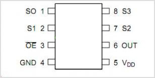
TSC230 Color Sensor

TSC230 - Color Sensor
Color Sensor TCS230 color sensor is a chip that works with the converting acceptance of a certain color of light emitted into the shape of frequency. TCS230 Color Sensor composed dri two main parts, namely a light-receiving section arranged in an array photodioda and Chaya koncerter this part to the frequency.


Basically the TCS230 Color Sensor is a light sensor which is equipped with light filters for RGB primary color (Red-Green-Blue) and light sensor without the filter with scale 8 bits for each of this part of the sensor.

Photodiode the TCS230 Color Sensor arrays arranged in 8 × 8 with the internal configuration of the photodiode. 16 photodiode for the light sensor with a red light filter. 16 photodiode for the light sensor with a green light filter. 16 photodiode for the light sensor with a blue light filter. And 16 photodiode for light sensor without a color filter. On the use of Color Sensor TCS230 we can choose the color sensor with a filter of what we want to set the configuration data S2 and S3.

Pin-Out TSC230
Pin-Out TSC230

Photodiode the TCS230 Color Sensor will issue a magnitude comparable with current levels of primary color of light that happened to him. This current is then converted into pulses with a frequency proportional to the amount of current. TCS230 Color Sensor Output frequency can be made by adjusting the scale of the configuration data S0 and S1 of the selector pins S0 and S1 Color Sensor TCS230.
Continue Reading[..]

Monday, April 8, 2013

TV Vertical Protectors

Vertical Protectors (another term surge protector or Vertical CRT Neck Guard or protector) . If the vertical deflection does not work, then the raster will glow a horizontal line. This can cause the picture tube phosphor layer was destroyed by fire when the aircraft be kept alive in the long term.

There are several types of system protectors, vertical relationships:
  • Protector surge protector is connected with x-ray to the horizontal which will trigger the horizontal oscillator is not working
  • Protectors gets connected to microcontrol that will trigger the "power off" so that the plane will turn off automatically or plane alive but raster becomes dark (brightnes level down).
TV Vertical Protectors
Vertical Protect
The workings of the system-vertical surge protector that can be found there are several kinds:

  • Using sampling pulses from vertical-out IC which is connected to microcontrol . If microcontrol  not receive these pulses the surge protector will work.
  • Using a sampling of the voltage supply Vcc-vertical IC connected to the IC microcontrol  using a diode. In the normal kondidi no voltage on the pin-IC microcontrol  protection. If the supply voltage Vcc or a short break then the voltage on the pin-microcontrol protection will come short to ground through the diode and trigger protection to actively work
  • Using the IC supply current sampling vertical-out that will actively work if the current exceeds supply. As the sensor protector installed here a series resistor and a transistor in the supply line where it works similar to the OCP.
Problems or possibilities that may cause the protector of vertically-active work:
  • Vertical IC-out short (broken)
  • No voltage supply to the vertical IC-out.
  • Vertical lines of the IC pulse-out to any part microcontrol  broken or damaged
  • Vertical deflection section does not work (damage to the IC)


Continue Reading[..]

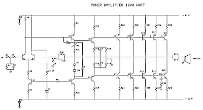
How to Create 1000 Watt Power Amplifier

Power amplifier has up to 1000 Watt power, this circuit made one channel only so if you want to create a stereo in it must be made one again, actually this is more suitable power amplifier in use for Sound System or outdoor, so if only in use for the house I think is less suitable.
Maybe youve seen or even have an active speaker and there is written 1500 watts PMPO (Peak Music Power Output), make no mistake this is different from Power Amplifier Active Speaker, I often dismantle such Active Speaker in it only a power with power no more than 150 watts by using the transformer 2-3 Ampere. PMPO is not a real power which is issued by the Power Amplifier, but counting all the speakers that there is, for example: if there are 5 pieces of speakers on each channel and each speaker has a power of 10 W then it is 100 W PMPO.
1000W Power Amplifier
1000W Power Amplifier schematics
1000W Power Amplifier
Part List 1000W amplifier
While this 1000 Watt Power Amplifier minimal use transformer 20 Ampere. And the output of Power Amplifier DC voltage contains approximately 63 volts, with currents and voltages of this magnitude, this 1000 Watt Power Amplifier will not hesitate hesitate to destroy your woofer speakers to connect. To overcome that then before the speaker on connects to 1000 Watt Power Amplifier must be in pairs Speaker Protector.

Actually if you want to create a Power Amplifier with great power does not have to make a Power Amplifier with great power. Example: you want to create a Power Amplifier with 10 000 Watt power. You do not have to assemble a Power Amplifier with power of 10,000 watts, but you assemble the power Power Amplifier Small but many, such as you assemble the Power Amplifier with 1000 Watts of power for as many as 10 pieces, it will produce 10 000 Watt Power Amplifier helpless.

Circuit uses power transistors pair of 5 x 5 x 2SA1216 and 2SC2922 and 2SC1583 use a differential amplifier that actually contains 2 pieces of transistors that are in containers together. Why use such built-in amplifier differental tujuanya so identical / similar, could have uses 2 separate transistors but can result in amplifier so it is not symmetrical.

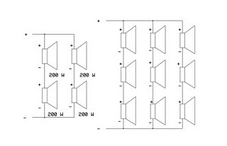
Tips combining speaker.

To get the speakers with great power combining techniques can be used in parallel series, combining each group of speakers should sepaker they will have the same impedance, the same type (Woofer, Mid Range or tweeter) and the same power. Number of merging these speakers should consists of 4 , 9, 16 ff, see picture
1000W Power Amplifier
Speaker wiring


Example: The number of speakers have 4 pieces each of its 200 Watt power generated will be a speaker at = 200 x 4 = 800 Watt. If there are 9 speakers 200 W then the result = 9 x 200 W = 1800 Watt.
Continue Reading[..]

Sunday, April 7, 2013

45 W Stereo Tube Amplifier

Stereo Amplifier with Tube
Stereo amplifier is very simple, consisting of 5 active components including the power supply it. Series Stereo Amplifier With Tube was prepared with 5 units trioda tube consisting of 1 unit tubes 5Y3 GT vacuum rectifier, 2 tube tube trioda 6SF5 GT high-mu tube 6k6 and 2 units which form the power beam amplifiers.


Power consumption for the circuit with a tube stereo amplifier is not more than 45 Watt. Current consumption for the circuit with a tube stereo amplifier is around 3A. A complete range of stereo amplifiers with this tube can be seen from the following series of images.

Stereo Amplifier With Tube


Sign Component Stereo Amplifier With Tube
  • R1, R10, R13 2.2M
  • R2 470K 1/2W
  • 1 Meg 1/2W R3
  • R4 220K 1/2W
  • R5 330 Ohm 2W
  • R6 220K 1/2W
  • R7 2.2Meg 1/2W
  • R8 1Meg 1/2W
  • R9 720 Ohm 20W
  • R11 33K 1/2W
  • R12 22K 1/2W
  • C1, C9 400V 0.005uF
  • C2 0.05uF 600V
  • C3 20uF 25V
  • C4 0.01uF 400V
  • C5 200uuF 400V
  • C6, C7 15uF 450V
  • C8 15uF 400V
  • T1 117V Primary, Secondary 350VCT, 2 × 6.3V
  • T2 7600 Ohm Primary, Secondary 4 or 8 Ohm
  • SW1 SPST Switch
  • SP1, SP2 12 "4 / 8 ohm
  • C8 in the series stereo tube amplifier with the above serves to reduce radio frequency interference and to optimize the work of a wild series of ampifier stereo with these tubes.

Continue Reading[..]

Mains Powered White LED Lamp

Did it ever occur to you that an array of white LEDs can be used as a small lamp for the living room? If not, read on. LED lamps are available ready-made, look exactly the same as standard halogen lamps and can be fitted in a standard 230-V light fitting. We opened one, and as expected, a capacitor has been used to drop the voltage from 230 V to the voltage suitable for the LEDs. This method is cheaper and smaller compared to using a transformer. The lamp uses only 1 watt and therefore also gives off less light than, say, a 20 W halogen lamp. The light is also somewhat bluer. The circuit operates in the following manner: C1 behaves as a voltage dropping ‘resistor’ and ensures that the current is not too high (about 12 mA).
The bridge rectifier turns the AC voltage into a DC voltage. LEDs can only operate from a DC voltage. They will even fail when the negative voltage is greater then 5 V. The electrolytic capacitor has a double function: it ensures that there is sufficient voltage to light the LEDs when the mains voltage is less than the forward voltage of the LEDs and it takes care of the inrush current peak that occurs when the mains is switched on. This current pulse could otherwise damage the LEDs. Then there is the 560-ohm resistor, it ensures that the current through the LED is more constant and therefore the light output is more uniform.
There is a voltage drop of 6.7 V across the 560-Ω resistor, that is, 12 mA flows through the LEDs. This is a safe value. The total voltage drop across the LEDs is therefore 15 LEDs times 3 V or about 45 V. The voltage across the electrolytic capacitor is a little more than 52V. To understand how C1 functions, we can calculate the impedance (that is, resistance to AC voltage) as follows: 1/(2π·f·C), or: 1/ (2·3.14·50·220·10-9)= 14k4. When we multiply this with 12 mA, we get a voltage drop across the capacitor of 173 V. This works quite well, since the 173-V capacitor voltage plus the 52-V LED voltage equals 225 V. Close enough to the mains voltage, which is officially 230 V.

Mains Powered White LED Lamp Circuit Diagram

Moreover, the latter calculation is not very accurate because the mains voltage is in practice not quite sinusoidal. Furthermore, the mains voltage from which 50-V DC has been removed is far from sinusoidal. Finally, if you need lots of white LEDs then it is worth considering buying one of these lamps and smashing the bulb with a hammer (with a cloth or bag around the bulb to prevent flying glass!) and salvaging the LEDs from it. This can be much cheaper than buying individual LEDs…
Continue Reading[..]

Saturday, April 6, 2013

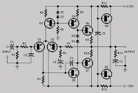
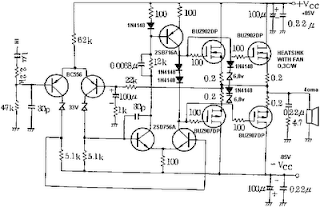
Mosfet Amplifier with power output 400W

See figure below its power amplifier using transistor mosfet as amplifier.
Mosfet Amplifier with power output 400W
Continue Reading[..]

Simple Voltmeter

This circuit provides a simple means to determine the voltage of a low-impedance voltage source. It works as follows. P1, which is a 1-W potentiometer, forms a voltage divider in combination with R1. The voltage at their junction is buffered by T1, and then passed to reference diode D1 via R3. D1 limits the voltage following the resistor to 2.5 V. An indicator stage consisting of T2, R4 and LED D2 is connected in parallel with D1. As long as the voltage is not limited by D1, the LED will not be fully illuminated. This is the basic operating principle of this measurement circuit.
Simple Voltmeter circuit diagram
Continue Reading[..]

Lambda Probe Readout For Carburettor Tuning

A lambda probe (or oxygen sensor) can be found on the exhaust system of most cars running on unleaded fuel. Having reached its normal operating temperature (of about 600 degrees Celsius!) the lambda probe supplies an output voltage proportional to the amount of residual oxygen measured in the exhaust gas.

This information is indicative of, among others, the air/fuel ratio supplied by the carburetor(s) and hence the combustion efficiency. In modern car (and motorcycle) engines, this information is used to (electronically) adjust engine parameters like ignition timing and fuel injection. The indicator described here is intended for permanent installation on a motorcycle of which the air/fuel ratio needed to be watched, with the obvious aim engine power tuning after fitting a different set of carburetors. Apart from this obvious technical use the unit’s bright LEDs will no doubt attract the attention of curious motorcyclists.

Lambda Probe Readout For Carburettor Tuning

At the local junkyard a single-wire lambda probe may be salvaged from a wrecked car. Once a suitable nut has been found, the probe can screwed into the exhaust pipe of the motorcycle, at about 30 cm from the cylinders.  Since we’re talking of welding and drilling in an expensive (chrome-plated) exhaust pipe, you may find that actually fitting the probe is best left to specialists!  The starting point for the design of a suitable electronic indicator is that in the noble art of carburetor tuning an air/fuel ratio of 14.7 to 1 is generally considered ‘perfect’, the range covering 16.2 to 1 (‘lean’) to 11.7 to 1 (‘rich’). The perfect ratio typically corresponds to a probe output voltage of 0.45 V. 

 Referring to the circuit diagram, that is the input level at which 5 of the 10 LEDs will light, including the green one, D5. If one of the red LEDs lights, the mixture is definitely too rich. Note that in general it is better to have a mixture that is a little to rich than one that’s on the lean side, hence a yellow LED lights between the green LED and the first red one. Also note that the engine needs to be at its normal operating temperature before a meaningful indication is obtained.
Author : P. G oossens
Continue Reading[..]

Friday, April 5, 2013

Adapter Network Diagram

Home Wiring Diagrams on Get More Information Regarding The Home Phone Wiring Diagram Using
Get More Information Regarding The Home Phone Wiring Diagram Using.


Home Wiring Diagrams on Home Wiring Fuses And Circuit Breakers Diagram   Circuit Schematic
Home Wiring Fuses And Circuit Breakers Diagram Circuit Schematic.


Home Wiring Diagrams on Home Wiring Diagram
Home Wiring Diagram.


Home Wiring Diagrams on Circuit Diagram House Wiring On Keywords House Wiring Diagram
Circuit Diagram House Wiring On Keywords House Wiring Diagram.


Home Wiring Diagrams on Xbr Cable Connection Schematic And Wiring Diagram   Circuit Schematic
Xbr Cable Connection Schematic And Wiring Diagram Circuit Schematic.


Home Wiring Diagrams on Result For Wiring Diagrams For Home Theater Systems   Page 1 Lookpdf
Result For Wiring Diagrams For Home Theater Systems Page 1 Lookpdf.


Home Wiring Diagrams on Channel Stereo Amplifier Wiring Diagram Schematics
Channel Stereo Amplifier Wiring Diagram Schematics.


Home Wiring Diagrams on Wii With Wii Lan Adapter Network Diagram
Wii With Wii Lan Adapter Network Diagram.


Home Wiring Diagrams on Free Wiring Diagrams   Download Free Wiring Schematics
Free Wiring Diagrams Download Free Wiring Schematics.


Home Wiring Diagrams on Home Electrical Blueprint
Home Electrical Blueprint.


Continue Reading[..]

Formal Cat5 Definition Reserves Extrawires

Wiring Diagram  Cat5 Cable on View Full Size   More 04 Silverado Wiring Diagram By Catha
View Full Size More 04 Silverado Wiring Diagram By Catha.


Wiring Diagram  Cat5 Cable on 940 Electrical System And Wiring Diagram 1994   Circuit Schematic
940 Electrical System And Wiring Diagram 1994 Circuit Schematic.


Wiring Diagram  Cat5 Cable on Ford Ranger Wiring Diagram Cable Harness
Ford Ranger Wiring Diagram Cable Harness.


Wiring Diagram  Cat5 Cable on Rj 11 4 Pair Phone Wiring Color Codes And Diagram   Circuit Schematic
Rj 11 4 Pair Phone Wiring Color Codes And Diagram Circuit Schematic.


Wiring Diagram  Cat5 Cable on Loud Speakers Cable Color Code 1 Rear Right Speaker Purple
Loud Speakers Cable Color Code 1 Rear Right Speaker Purple.


Wiring Diagram  Cat5 Cable on Wire A 10baset Or 100baset Connector With Cat5 Cable Using Eia Tia 56b
Wire A 10baset Or 100baset Connector With Cat5 Cable Using Eia Tia 56b.


Wiring Diagram  Cat5 Cable on The Formal Cat5 Definition Reserves The Extra 4 Wires So
The Formal Cat5 Definition Reserves The Extra 4 Wires So.


Wiring Diagram  Cat5 Cable on Bhagwan Photos  Cat5 Cable Wiring Diagram
Bhagwan Photos Cat5 Cable Wiring Diagram.


Wiring Diagram  Cat5 Cable on The Exact Sequence Represented In The Wiring Diagram Labeled 568b
The Exact Sequence Represented In The Wiring Diagram Labeled 568b.


Wiring Diagram  Cat5 Cable on If A Cable Has 568a Color Wiring On Both Ends Then It S A Straight
If A Cable Has 568a Color Wiring On Both Ends Then It S A Straight.


Continue Reading[..]